Print Page
|
MD41 Series ACU's
The Perfect Solution for a New Approach to Flying
The MD 41 combines navigation source switching to the primary
CDI and HSI with key GPS selection functions in a standard ATI
panel-mount unit only 4.65" deep. Up to seven separate relays
and three switches are replaced by this single, compact unit,
making installation simpler, faster and more economical. Lighted
push buttons and easy-to-read annunciators make the MD 41
popular with pilots as well as technicians. Push buttons provide
plenty of tactile feedback, ensuring safe, accurate operation,
even in bumpy IFR conditions.
Pilots can fly with confidence, knowing that the MD 41 has
been certified to TSO C129 standards, meeting the new FAA
field approval requirements.
|
| |
| |
MD 41-1000 SERIES FEATURES ACU OPERATES SPECIFICATIONS |
Introducing Our Newest Development In Gps Control, "Slim Line Pro" ACU
For technicians, this compact, lightweight system greatly simplifies the
installation of IFR approach-certified GPS units. For pilots, the MD41-1000
helps get the most out of their GPS, both en route and on approach.
Only 2.25" or 2.75" wide and 3.25" deep, the MD 41-1000 is available
for either horizontal or vertical installation and is approved under TSO
C129 to 55,000'. What's more, 24 user-defined relay poles are available
in the remotely mounted switching unit. A complete installation kit with
MIL-spec connectors further adds to installation flexibility and simplicity.
All annunciators and push buttons are integrated in a single unit while
the relay are remotely mounted, enhancing safety and minimizing pilot
workload. Push buttons are internally lighted and annunciators are
photocell dimmed, making them easy to see in any lighting condition.
Models are available for all approach-certified GPS systems. When
it's time to plan your next GPS installation, take a close look at the
MD 41-1000 ACU.
|
 | TSO C129 approved to newest FAA standards |
| Horizontal or vertical configuration |
| Proven daylight readability |
| Annunciators dim/brighten automatically |
| Push-button brightness controlled by instrument lighting rheostat |
| Connector/installation kit included |
| 19-pole relays, gold-plated contacts |
| ILS frequency override selectable |
| Built-in annunciation self-test |
| NAV/GPS. Alternate action switch. Selects either NAV or GPS navigational information of HSI or CDI |
| GPS/APR. Momentary switch. Arm GPS approach mode |
| OBS/LEG. Alternate action switch. Selects either OBS or LEG mode |
| LAMP TEST. Momentary switch. Test annunciator lamps. How the |
|
Pushing the NAV/GPS switch selects the navigation source (VOR/ILS/LOC
or GPS) to be displayed on the HSI or CDI. Although it may be displayed
on the GPS unit's built-in CDI, course information is also displayed on the
panel-mounted HSI or CDI when executing an approach utilizing GPS
navigational data.
Pushing the GPS/APR switch arms the GPS for the selected approach.
Course guidance direct to the initial approach fix and automatic
approach waypoint sequencing are then provided. The GPS receiver
automatically switches from ARM to ACTV (Active) as the aircraft
nears the final approach fix.
Pushing the OBS/LEG switch toggles between OBS and LEG. In OBS
mode, the magnetic course to be flown "To" or "From" a waypoint is
selected using the OBS knob on the HSI or CDI, similar to VOR navigation.
In LEG mode, the GPS receiver automatically sequences between
waypoints contained in the receiver's active flight plan.
The MSG annunciator is automatically lit when the GPS receiver initiates
a message (airspace warnings, steep turns, etc.) MSG annunciation is
automatically extinguished by the GPS receiver. The WPT annunciator
flashes as the active waypoint in the GPS receiver is approached along
the route of flight.
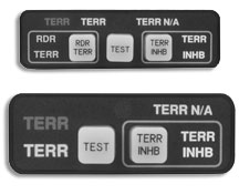
Vertical Mount for Flexibility
The MD 41 ACU is available in a convenient vertical mount for added
installation flexibility. Also shown above are MD 41 versions for GPS
systems not requiring the OBS/LEG or GPS/APR selector buttons.
|
| TSO Approval |
TSO C129 |
| Applicable Documents |
RTCA DO-160C, DO-208 |
| Operating Temperature Range |
-20°C to +70°C |
| Humidity |
95% |
| Altitude Range |
0 to 35,000' |
| Vibration |
Cat M & N |
| Operational Shock |
Rigid mounting,
6 G operational.
15 G crash safety |
| Design |
All solid-state |
| Power Requirements |
MD 41-( ) 14 VDC: .065 AMPS
MD 41-( ) 28VDC: .40 AMPS |
| Relay Contact Current Rating: |
2 AMPS DC |
Available Relay
Poles (SPDT): |
19-poles |
| Mounting |
Panel-mount ATI |
| Width |
3.5" |
| Height |
1.350" |
| Depth |
4.625" |
| Weight |
0.75 lbs. |
|
|
|
|
|